High Safety 3kw On Grid Maglev Wind Power Generator By Intertek CXF-3000W
High Safety 3kw On Grid Maglev Wind Power Generator By Intertek CXF-3000W
The Maglev Wind Power Generator CXF-3KW-B is regarded as the milestone maglev wind turbine, integrated with appearance design, utility design, electrical and electronic engineering, power machinery, aviation atmosphere engineering, wind tunnel test, magnetic suspension technology, lightning protection technology and computer simulation analysis, and made of light aluminum alloy, titanium alloy and stainless steel, besides, the generator can be started in the breeze and continuously and steadily output full power . The maglev wind turbine CXF-3KW-B adopts the magnetic suspension technology and the magnetic force of the super magnet to suspend a motor coil in a certain space so that the motor rotates to incise a magnetic force line so as to send out alternating current in wind without any mechanical friction, thus the generator has the advantages of high-efficiency generation and steady operation.
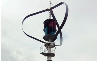
The Maglev Wind Power Generator mainly includes a blade, an air duct, a generator and a lightning rod. The hollow flat strip-shaped component on the outermost layer of the wind turbine is acted as the blade of the wind turbine, the crossed section thereof is the aircraft wing structure which can generate elevating force formed into an angle with the motion direction in flow so as to generate rotary power by the wind turbine.
The center of the wind turbine is provided with an S-shaped opening cylinder made of two semicircular aluminum alloy plates, the cylinder is divided into upper and lower nodes which are respectively provided with an opened air duct, and the S-shaped air duct is fixed to a vertical shaft of the wind turbine, so that wind can access through the windward side of the S-shaped air duct to pass through the gap from the center shaft of the wind turbine, and the wind again enters into the other windward side of the S-shaped air duct to rotate the wind turbine, by this way, the wind can be reutilized and the wind turbine can be rotated in the breeze.
The top of the vertical shaft is provided with the lightning rod whose bottom is connected with the wind turbine and effectively grounded by an installing rod, and the lightning rod is used to prevent the generator from lightning stroke, thereby ensuring the wind power system is normally operated.
Safety coefficient
In order to ensure that all structural components of the wind power generator don’t affect the structure within the normal service life under the normal wind condition due to structure fatigue or damage the system structure under the limit wind condition due to structure limit intensity, according to the National Standards of Small Vertical Shaft Wind Turbine (GB/T29494-2013) and requirements of IEC 61400-2, during design, the maximum rotation speed ωmax of the CXF-3KW-B has been tested and confirmed, and ωmax is less than 1.5ωdesign and regarded as the upper limit of the rotation speed, namely the condition (I) is that ωmax of the wind turbine has been tested and confirmed, and ωmax is less than 1.5ωdesign and regarded as the upper limit of the rotation speed; the condition (II) is that ωmax is more than 1.5ωdesign, or ωmax of the wind turbine has been not tested and confirmed, and the upper limit of the rotation speed adopts 1.5ωdesign.
Overview of control system and safety system
In operation, the Maglev Wind Power Generator may affect system stability so as to further damage personnel and environment, thus the wind power generator CXF-3KW-B includes the following functions in design :
a) Inherent over-speed protection functions of wind rotor and blade: because the air duct involves in the resistance one and the blade refers to the lifting blade, when the wind power generator is beyond the design rotation speed, the resistance of the air duct is continuously increased, the power of the peripheral wing-shaped blade isn’t increased in a certain wind speed, the rotation speed of the wind turbine can be controlled by the air duct and the blade.
b) Control and protection functions of power control system: when the rotation speed of the wind turbine is beyond the preset brake rotation speed due to the greater wind speed, the controller gradually increases the duty cycle of the PWM signal in the Boost boosted circuit so that current and resistance of the wind turbine can be increased to slowly reduce the rotation speed of the wind turbine,
when the rotation speed is reduced to the enough low level, the built-in switch is closed by the controller to result in the three-phase short circuit of the wind turbine, and the whole braking process is completed. The brake is automatically relieved after three minutes. If four-time consecutive brake is occurred within 15 minutes, there is strong sustained wind, and the brake is automatically relieved after four hours.
c) Protection functions of manual mechanical brake: the bottom of the CXF-3KW-B wind turbine is provided with a manual brake mechanism, before violent typhoon occurs or when the wind turbine rotation speed is beyond the design rotation speed, the manual brake system is manually pulled down such that the wind turbine rotation speed is gradually reduced to achieve the brake, by the way, the wind turbine system can be ensured in safe operation.
Description of load conditions
In order to effectively evaluate security and structure strength of the Maglev Wind Power Generator in operation and prevent the wind turbine from possible structure limit intensity or structure fatigue in actual operation, the whole structure of the wind power generator is rationally calculated and analyzed. During load calculation, the maglev wind turbine CXF-3KW-B can be mainly divided into the resistance wind rotor and the lifting wind rotor.
To the simple load calculation model of the S-shaped resistance wind rotor of the vertical shaft wind power generator, various loads are calculated according to various parameters.
The resistance Savonius wind rotor mainly includes the following load:
a) Fatigue load
b) Load generated during normal operation of wind turbine
c) Maximum centrifugal force load
d) Load caused due to short circuit of generator during operation
e) Load generated by wind turbine from operation to stoppage
f) Load occurred by limit wind in one-year cycle
g) Load occurred by limit wind in 50-year cycle, including still and idle load
h) Load during transportation, assembly, maintenance and repair
See Drawing-Connection Drawing of Air Duct, Blade And Tower for All Structures.
To the simple load calculation model of the lifting blade of the vertical shaft wind power generator, various loads are calculated according to various parameters.
The lifting wind rotor (Darrieus) mainly includes the following load:
|
a) |
Fatigue load |
|
b) |
Load generated during normal operation of wind turbine |
|
c) |
Maximum centrifugal force load |
|
d) |
Load caused due to short circuit of generator during operation |
|
e) |
Load generated by wind turbine from operation to stoppage |
|
f) |
Load occurred by limit wind in one-year cycle |
|
g) |
Load occurred by limit wind in 50-year cycle, including still and idle load |
|
h) |
Load during transportation, assembly, maintenance and repair |

